

Lando Norris locking up the brakes in 2022 pre-season testing at Bahrain
Braken’ Ain’t Easy - Using data and the theoretical braking potential to reduce lap times
By Trav Mays
Drivers are faced with a very difficult task, trying to predict the level of grip they have in an ever changing environment isn’t easy, add to this other competitors and you have a recipe for mistakes. When it comes to braking, these mistakes lead to either over shooting the corner, braking too early, or locking up the tyres, all of which hurt that lap time, but more importantly they reduce the driver’s confidence in the car, affecting all proceeding lap times.
In this article we are going to look at using data and a braking model that converts the theoretical maximum braking force to brake line pressure to tackle two of these braking mistakes, braking too early (softly) and locking up the tyres. By building this braking model, we can not only monitor the actual braking performance at the track, but we can tailor the setup to that track before we show up to the race.
I’m going to quickly go over the theoretical maximum braking force here and then get into some examples of the types of analysis you can do with the results. If you’d like a more detailed explanation of how to actually do this, or you’d like the Race Studio or Motec i2 equations, head over to my blog post titled “A step by step guide to building a braking model of a car”.
There is a lot to take into account before set up changes are made, depending on how advanced your model is and the amount of real world model validating you have done, the level of confidence you give the results will vary. The analysis process described here should be used as another tool in your belt to compare potential setup alterations, not as a standalone model.
Theoretical maximum braking force
Whenever brakes lock up, the total braking force has been exceeded, more has been asked for then the current load and tyre can give.

We have just two variables here, but both are just as important as the other and are just as loaded. Unfortunately creating a detailed tyre model isn’t realistic for most teams, but with a good dynamic weight transfer model and some calibrating, these teams can still increase the accuracy of the results substantially.

![Effect of (from top left) load [1], temp [2], slip ratio [3], and speed [4] on a tyre’s coefficient of friction](https://blogger.googleusercontent.com/img/b/R29vZ2xl/AVvXsEhVR9pN3l20red2jAkLz3AfsvtIQd2eDwTbJ8S19HzQegNV-W2995mKjifO4ZCgzHtnrhujow7VvyZPP02FOvdwlaNvvptcde95Wx1gCINQNVBLfX0xuWYT6EMaKsMg22xx8TbbUkHXZYlOQd7-FIuPZEC-CMNG8NchAF6Fk-5In-fH7JUHerXpDUMN/s16000/Pic%202.png "Effect of (from top left) load [1], temp [2], slip ratio [3], and speed [4] on a tyre’s coefficient of friction")
Effect of (from top left) load [1], temp [2], slip ratio [3], and speed [4] on a tyre’s coefficient of friction

Formula Ford Max theoretical front and rear brake line pressures vs actual brake line pressures

Formula Ford aerodynamic coefficients
The next thing you probably noticed, is the rear measured brake line pressures are very close to the theoretical maximum. They are running an almost 50/50 brake bias split (both peeking around 400psi), but if there were to dial in slightly more front bias, they will be able to take advantage of the load shift, allowing them to slam on the brakes harder without fear of locking up the rears. This will give them the ability to break later, reducing lap times and opening up more passing opportunities. It will also be a far safer set up, as locking up the rear tyres is a lot less controllable then the fronts.
Here I have used the data to optimise the brake bias set up at a given track, but that’s not all you can do once you have built the model. You could narrow it down to each corner, allowing you to optimise the brake bias setting or how hard you press the brakes in every corner of the track. You could use it to see the impact of changing the set up, tyres, brake pads, callipers, lines, wheel size, tyre size, tyre pressures, tyre wear, fuel load, etc, before you arrive on race day. Below shows the effect of changing the weight distribution on the left and the effect of a different tyre on the right.
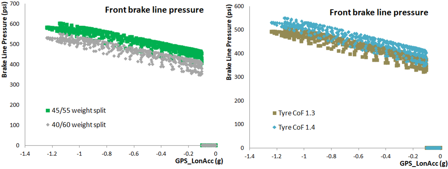
Highlighting other potential analysis ideas, weight distribution left, and different tyres right
If you’d like to increase the accuracy of your model, below are a couple ideas
Thanks for reading and I hope you have a great day.


We have just two variables here, but both are just as important as the other and are just as loaded. Unfortunately creating a detailed tyre model isn’t realistic for most teams, but with a good dynamic weight transfer model and some calibrating, these teams can still increase the accuracy of the results substantially.
Dynamic Weight
The load or weight on each tyre varies as we ask different things of a car, accelerating, braking, steering, or a combination of any of those causes the weight to shift from one wheel to another. Slamming on the brakes for example, causes the car to pitch forward, this pitching increases the load on the front axle and with it our braking potential. But it’s not that simple. Depending on how fast we are going, how hard we press the pedal, or whereabouts we are on the track, our braking potential will change. The more we are able to model, the more accurate and useful the results.
Tyre model
A tyre’s coefficient of friction changes due to load, temperature, slip ratio, slip angle, speed, inflation pressures, the moon cycle, the day of the week, everything alters the coefficient of friction, it’s very fragile. So depending on how advanced your tyre model is, you can add all of that, part, or none in this step, and simply use the effective value given to you by the manufacturer. Even without a detailed tyre model, we can still get close by spending a little more time validating the model with real world data.
If you’d like to learn more about a tyre’s coefficient of friction, head over to my blog to check out the series on tyres, link here
If you’d like to learn more about a tyre’s coefficient of friction, head over to my blog to check out the series on tyres, link here
Effect of (from top left) load [1], temp [2], slip ratio [3], and speed [4] on a tyre’s coefficient of friction
Example
Below I have plotted the front and rear theoretical brake line pressure for a formula ford. I have assumed a flat road and compared the load transfer, drag, lift, and the wheel inertia in blue, to just load transfer in orange, and to the measured brake line pressures in green. As you can see, keeping it simple and just using the load transfer, if you don’t have much aero, can get you a fairly accurate result.
Formula Ford Max theoretical front and rear brake line pressures vs actual brake line pressures
The first thing that stands on the plots is the front brake pressure has a range of theoretical brake line pressures for the same long G value, whilst on the rear it’s a straight line. That is because for this formula ford, the lift being generated in the rear is almost non-existent.
Formula Ford aerodynamic coefficients
The next thing you probably noticed, is the rear measured brake line pressures are very close to the theoretical maximum. They are running an almost 50/50 brake bias split (both peeking around 400psi), but if there were to dial in slightly more front bias, they will be able to take advantage of the load shift, allowing them to slam on the brakes harder without fear of locking up the rears. This will give them the ability to break later, reducing lap times and opening up more passing opportunities. It will also be a far safer set up, as locking up the rear tyres is a lot less controllable then the fronts.
Here I have used the data to optimise the brake bias set up at a given track, but that’s not all you can do once you have built the model. You could narrow it down to each corner, allowing you to optimise the brake bias setting or how hard you press the brakes in every corner of the track. You could use it to see the impact of changing the set up, tyres, brake pads, callipers, lines, wheel size, tyre size, tyre pressures, tyre wear, fuel load, etc, before you arrive on race day. Below shows the effect of changing the weight distribution on the left and the effect of a different tyre on the right.
Highlighting other potential analysis ideas, weight distribution left, and different tyres right
Clearly there is more to think about when deciding a car’s set up, but this gives you another tool in your belt to make more informed decisions.
If you’d like to increase the accuracy of your model, below are a couple ideas
- Instead of total car static weight, you can use the adjusted fuel load weight as the fuel is burnt. You could keep this simple and do a linear relationship, or depending on your fuel burn model, you could use the value you calculated by recording the amount of fuel and its temperature as it goes in and out of the car. Cross reference this with the ECU measured value, and you now have a fuel burn model that can be used to take into account in, out, and safety car laps.
- The position of the CoG will change with different suspension setups and as the fuel is burnt (especially if you have a rear mounted tank), taking these into account will help to paint a more realistic picture.
- If you have an aero map of your car and damper pots, you can better model the lift or downforce being generated as the car’s ride height and rake change.
- Recording the direction and velocity of the wind allows you to either add or minus it from the car velocity, giving you the option to correct for it.
- If you are able to log the gear selected, you can include the inertia from the complete driveline and the engine
- The brake pad and rotor coefficient of friction doesn’t stay constant, it will vary with temp
- I have assumed there are no brake line pressure losses in the system, the pressure used to move the pistons, creating the clamping force, is the same as what is being measured upstream. Clearly this isn’t the case, so there is potential for more accuracy here, especially if we included temperature effects with the following:
- Pad compressibility,
- Calliper flex,
- Fluid compressibility,
- Hose expansion,
- Connection losses, and
- Pipe length losses
- If you have the engine torque map of your car, you can also include engine braking.
- Brake fade hasn’t been taken into account, I’m not sure of a way to do this reliably and accurately enough, but I'm sure someone knows how to. If you do, I'd love to hear it.
As I said earlier If you’d like to go through a step by step guide or you’d like all the formulas in one place, head over to this blog post “A step by step guide to building a braking model of a car".
I hope you enjoyed it, if you did, have any comments, suggestions, or noticed I made a mistake, let me know in the comments, get in contact via email, or connect with me here, I’d love to hear it. If you’d like to read more, check out some of my other articles or myyoutube site.
Thanks for reading and I hope you have a great day.
By Trav Mays
Previous Post Next Post


No comments:
Post a Comment